Subtitle: Simple and Safe Puncture (Method choice: CT-, Fluoroscopy-, or Ultrasound-guided)
14.11.25.
Table of Contents:
Chapter 1: The Various Aspects of Radiation Protection; (follows right after this table of contents)
1a Strict distinction between construction and application technology
1b Radiation protection of the patient or the examiner
1c Confusing abundance of parameters
1d Different radiation protection for different methods
Chapter 2: Radiation Protection in X-ray Imaging (Fig. 1 -10)
Chapter 3: Fluoroscopy (FL), (Fig.11 -22)
3a FL with direct patient contact
3b Remote control
3c The rules in radiation protection
Chapter 4: Computed Tomography CT (Fig.23 – 25)
4a Most important dose size: Dose-Length Product (DLP)
4b ALARA principle – critical considerations for “Low-dose”
4c Indications and alternatives to CT
Chapter 5: Interventions, Method Choice: Fluoroscopy (FL)
or Computed Tomography (CT),(Fig.26 -32)
5a Puncture under fluoroscopy?
5b Puncture in CT
*****************************************************
TABLE: 4 important doses, depending on whether single dose or protracted dose, whether whole-body or local radiation
| Single Dose | Protracted Dose | ||
| Whole-body | Lethal Dose 50% = 4Gy= 4Sv | Effective Dose in mSv: Lifetime Dose = 400 mSv; Maximum Annual Dose 20mSv |
|
| Local | Epilation Dose = 4Sv | Partial Body Annual Dose: Skin/Hands/Feet = 500 mSv |
Chapter 1: The Various Aspects of Radiation Protection
1a Distinction Between Construction and Application Technology
We should make a clear distinction between
- what our partners, the companies, install (with acceptance testing etc.) and
- the manner of application (described and determined in service instructions).
The first point concerns the industry, the second the medical users.
Both are regulated by ordinances. The radiation protection officer must take care of both.
But not everything is regulated; some decisions remain our responsibility as the accountable parties, and must be managed with common sense and expertise. Some measures are sensible and advisable, even if not mandated by ordinance.
We are responsible, both as users and manufacturers. Both should think and act beyond fashion and the market. Often, a procurement goes like this: Two veteran doctors take a trip to X, where they are shown, for example, a fluoroscopy device intended mainly for interventions. Both are impressed by the “sharp” images. Their praise enters into the decision and order. These two have no idea how high image quality (also) comes about: High and very high doses make low noise and thus a very good image impression. In a high dose, the unknowing audience is dazzled. Responsible radiation protection means understanding such relationships.
Another example: The two potential buyers visit a CT machine. They gain a – objectively correct – impression of the quality of the images. They are unaware, however, that the low noise was bought at the expense of high milliamperes (mA). It would have been appropriate to have shown them images with a low tube current. This would have been especially justifiable at the lung and heart. With CT using spiral technology, attention should be paid to the pitch factor. Is the table feed not too small in relation to the slice thickness? Does this produce an impressive but unusual (and from a radiation protection point of view unnecessary) quality? There have been great advancements; we should insist that these be objectified in the form of mandatory and automatically recorded cGy x cm
1b Radiation Protection of the Patient or the Examiner
The X-ray Ordinance (RöV) deals with personnel. Employers and supervisors are obligated to provide the prerequisites for radiation protection. Increasingly, the patient is also considered in the regulations.
It is often claimed that there is hardly any correlation between patient dose and examiner dose during different examinations. This is not correct, at least in a didactic sense. Sure, there can be mistakes that have the peculiarity of going to the detriment of either the patient or the examiner. Most often, however, it is a “both and”: In a specific examination (e.g., heart angiography), the dose for both patient and examiner rises almost equally over the course of the examination. If one theoretically stops the examination in the middle of the time, the dose for both patient and examiner is halved approximately.
In my view, it is quite sensible not to strictly separate radiation protection for the patient and the examiner. What benefits one can also benefit the other. Under no circumstances should the impression arise that radiation protection for the examiner is achieved at the expense of the patient’s radiation protection.
1c Seemingly Confusing Parameters
What should one aim for: Equivalent dose in mSv or area dose product cGy x cm² (FDP) In X-ray and fluoroscopy examinations?
The area dose product FDP is a purely physical, easy-to-measure size and very suitable for determining patient exposure. For the latter, the cGy x cm² is a measure that
Chapter 2: Radiation Protection in X-ray Imaging (Fig. 1-10)
Chapter 2: Different Radiation Protection in Various Methods: a. Conventional X-ray Imaging, b. Fluoroscopy (FL), and c. Computed Tomography (CT).
We first focus on conventional X-ray imaging and demonstrate its diversity with images 1-10. However, distinguishing the other methods is important because the primary measure for radiation protection differs between these techniques.
In imaging and FL, the DFP: cGy x cm²
In CT, the DLP: cGy x cm
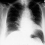
Fig.01: Thorax in standing position.
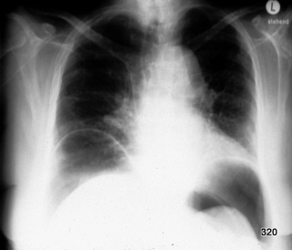
Diagnosis: Free Air in the Abdomen.
The diaphragms are not only represented by a simple silhouette but show a silhouette above and below, indicating the “bowl sign” (see article “Thorax and Pleura, Radiology”).
Fig.02: Same diagnosis, different technique: Free Air in the Abdomen.
Abdominal overview in lateral position; horizontal beam projection.
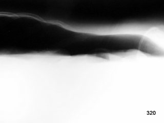
We must achieve a specific dose on the film; otherwise, the film will be underexposed, leading to significant loss of information.
With storage phosphor plates or image intensifiers, the optical impression can seemingly be balanced, but the image noise is high, and the quality is poor. For good reasons, we do not accept such underexposed images in conventional X-ray imaging and increase the dose for a voluminous patient.
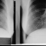
Fig. 3: Two overview images are mirrored. Both depict the right lung, showing a progression within four hours!
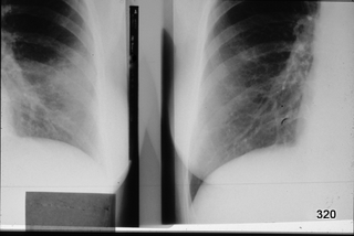
The left image shows an opacity; the heart silhouette is blurred, and the vessels are largely obliterated. On the right, the short-term progression. What type of lung opacity can improve so quickly?
Condition following lavage during a bronchoscopy.
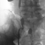
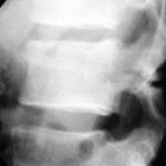
Fig. 4: A classic case. Severe rear-end collision. Lateral X-ray of the lumbar spine: Fracture through the pedicles and the vertebral body. What is the English term for this?
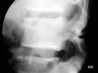
Seatbelt Fracture.
It is essential to recognize this image, although nowadays, in such trauma scenarios and likely clinical suspicion of a potentially unstable fracture, a CT scan is typically performed early—ideally in the trauma bay itself.
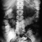
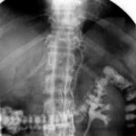
Fig. 5: An Oddity. Abdominal overview in constipation. Colon distended by a swelling bismuth preparation.
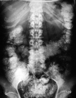
Fig. 6: Close-up of this metal-dense material in the colon.
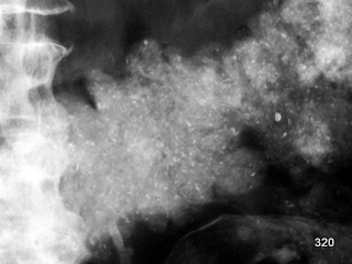
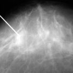
Fig. 7: Puncture and biopsy of mammographically suspicious findings.
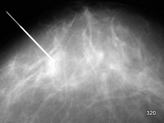
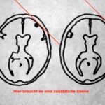
Localization requires a second plane. – These important techniques were not further illustrated in this article.
Fig. 8: Variety of procedures utilizing X-rays. Lymphography
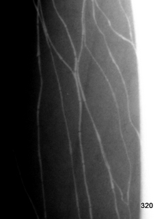
Fig. 9: Artificial artifact from an attempted lymphography (iatrogenic artifact, see Article 13).
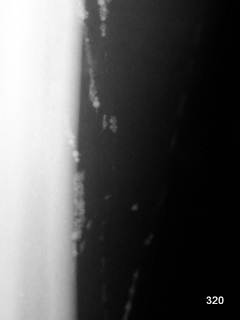
Contrast agent has entered the blood vessels; this must be identified quickly to minimize side effects.
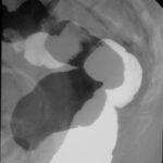
Fig. 10a: X-ray Defecography. Imaging of the rectum.
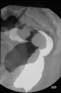
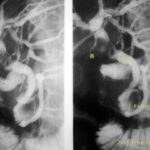
Black Bowel: Resting with pelvic floor tension; note the indentation at the lower boundary. White Bowel: During rectal emptying. Both images A and B are subtracted; one phase appears black, the other white, and the skeleton is nearly eliminated, avoiding overlap.
Diagnosis combined with clinical findings: Moderately pronounced anterior rectocele. Recommendation: Biofeedback, no indication for surgery.
This technique (Fig. 10a) was developed and applied by the author, initially for radiation protection purposes. Some practitioners took several hundred camera images for this type of examination. With this new method, it was possible to obtain diagnostically important information with significantly lower doses. Nevertheless, X-ray examination in such an inherently extensive region, with significant bone overlap, presents a particular challenge for radiation protection. A phantom specifically designed for this region was constructed, and experimental investigations were conducted. The results can be found in the following chapter.
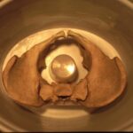
Fig. 10b: Phantom for self-experiments: Dose in imaging and fluoroscopy.
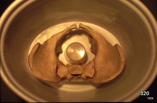
A water tank simulates the soft tissues, and a central vessel represents the rectum.
The “ALARA” principle applies to all X-ray methods. It states that the examiner should aim to achieve the greatest possible benefit with the lowest possible radiation exposure. In this department, X-ray examinations of the pelvis played a significant role due to the clinic’s orientation. Therefore, the challenging radiation protection in the pelvic region was deemed highly important.
The dose area product is an important, simple, and practical measure for the patient’s radiation protection (cGy × cm²).
The list of factors influencing the dose has been shown in many publications; it is discussed and illustrated in the following article: scatter radiation, sufficiently high kV, appropriate filtration, etc.
The following is an own experiment with X-ray imaging: Phantom see Fig. 10b; research question:
How much % can I save if a is used instead of b?
Reduction of the dose area product (DAP) when specific parameters are changed:
| 100 kV 125 kV Minus stage 10 x 10 Small focus |
instead of 75 kV instead of 100 kV instead of “Standard” instead of 16 x 16 cm instead of large focus |
40% 76% 66% 50% 0% |
|
| 0.2 g BaSO₄/ml | instead of 2 g/ml | up to 33%! | |
| Object- Image intensifier 0 cm |
instead of 20 cm | 84% |
At the end of the last chapter, an experiment was presented. It dealt with X-ray imaging and was suitable for demonstrating errors in imaging techniques. Conversely, it also showed the potential gain through higher kV. Even above 100 kV, further improvements can be expected.
In collimation, the gain is not as significant as might be expected from the area, but the dose savings are still considerable.
It is crucial in this imaging technique that the contrast agent in the rectum does not cover the ionization chamber. In this case, the automatic exposure control reports: “An object of very high density/atomic number is present here” and adjusts the mAs accordingly. Strong dilution of the contrast agent has a pronounced effect on radiation protection in such cases.
It is essential to leave no gap between the object and the image intensifier, as this would waste dose and image quality.
In summary, with this (intentionally careless) imaging technique and not entirely modern equipment, 200 to 300 cGy × cm² per image was required.
What happens if all the mentioned points are observed? These factors combine in their positive effect: 20 to 30 cGy × cm² per image.
The following text and examples with images deal with X-ray fluoroscopy.
Chapter 3: Fluoroscopy. Including Targeted Imaging under Fluoroscopy (Fig. 11-22)
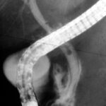
Fig. 11: Bile ducts and pancreatic duct filled with contrast agent using the endoscope with fluoroscopy assistance = ERCP.
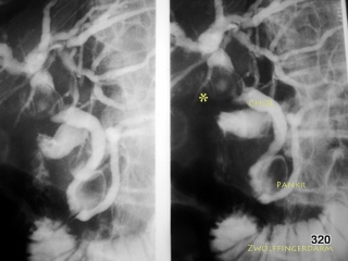
CHOL = Common bile duct. PANKR = Pancreatic duct. The endoscope has been removed in the meantime.
The common bile duct originates from many hepatic branches via the hepatic duct. The cystic duct, which drains the gallbladder, enters this system laterally.
A large, shell-like calcified stone is lodged in the cystic duct, not only blocking the cystic duct itself but also compressing the other ducts mentioned. Inflammation and scarred strictures are the result = Mirizzi Syndrome.
Fig. 12: Rare case of bile duct injury during endoscopic filling (ERCP).
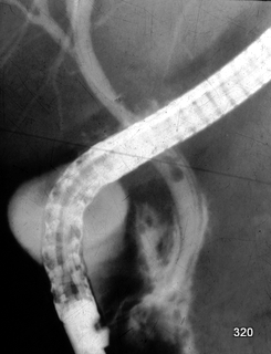
During fluoroscopy, contrast medium is observed early not only within the bile duct wall but also outside of it. The dark line on both sides of the contrast-filled pathways corresponds to the wall structure of the bile duct (choledochus); this is a pathological finding that must serve as an immediate alert signal!
Subchapter: 3a.
Fluoroscopy with Direct Patient Contact
One of the advantages of all forms of fluoroscopy is the temporal resolution, overcoming the limitation of an image frozen at a specific moment. Additionally, it is easy to vary the planes to obtain a spatial impression.
A brief historical note: In fluoroscopy devices constructed up to the mid-20th century, the screen geometrically linked to the tube could be moved without manual contact with the patient.
For many examiners, fluoroscopy with direct patient contact was familiar and routine. With the introduction of image intensifier television systems, little initially changed. The primary benefit for the examiner was the elimination of the need to adapt to darkness. For the patient, it was also a significant relief to not have to undergo the examination in the dark, which often caused considerable anxiety despite thorough explanation. The advantages in radiation protection were substantial.
The psychological benefits of working directly with the patient were and remain undeniable. Thus, the remote-control fluoroscopy systems, which allowed the examiner to maintain greater distance, presented a completely novel and unsettling experience for most patients. The physical presence of the physician can alleviate patient anxiety. Examiners value this advantage in all geographic and endoscopic procedures requiring fluoroscopy. However, this assumes that the entire examination process is prepared through personal, explanatory, and reassuring dialogue. Often, beyond mere verbal explanation, the movement sequence must be demonstrated and practiced. Even a simple body rotation can be significantly challenging for patients unfamiliar with the procedure.
The following principle still applies to all forms of fluoroscopy: Physicians appear uncertain and unfocused if they have not mastered the operation of the “machine” thoroughly. They must concentrate on the patient and their virtual image; it is unthinkable and negligent for them to simultaneously search for controls.
The “traditional” fluoroscopy technique, where the examiner remains close to the patient, is indispensable for angiographies (vascular imaging) and most interventional procedures, at least during certain phases of the examination.
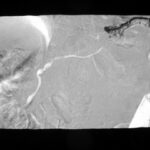
Fig. 13: Post-traumatic condition with extensive abdominal injuries. Surgical removal of the spleen. Non-healing fistula tract in the left upper abdomen.
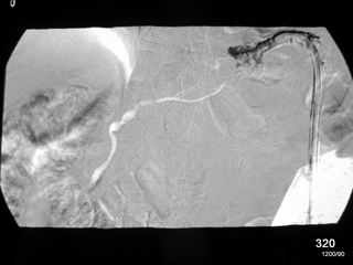
This fistula tract was filled with contrast medium under fluoroscopy. In other words, a skin fistula of the pancreas.
The image is a subtraction image showing an early and slightly later filling: It clearly highlights the pancreatic duct.
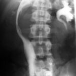
Fig. 14: In the case of obstruction of the urinary tract near the right kidney, contrast imaging of the right ureter from below:
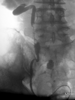
3 cm long, highly irregular narrowing at the level of the 5th lumbar vertebra (L5). This is a case of ureteral carcinoma.
Black and white are inverted in this image = inversion.
Subchapter: 3b Remote-Controlled Fluoroscopy
Nowadays, the goal is to position the patient in a defined/standardized manner on the table and move the “machines” around them. This is common in CT, (MRI), radiotherapy, and also in fluoroscopy. For the latter, we refer to “remote-controlled fluoroscopy.”
In the best-case scenario, the examiner’s dose approaches zero.
However, the above-described issues with patient cooperation are not resolved by remote control. The patient’s uncertainty and fear are often exacerbated. The solution lies in a clear understanding of the patient’s concerns. Everyone can contribute here: referring physicians, nurses, transport staff, radiology reception, and radiologic technologists. However, the primary responsibility lies with the examiner.
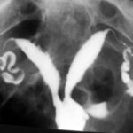
Fig. 15: Imaging of the uterine cavity and fallopian tubes: A developmental variant, the bicornuate uterus.
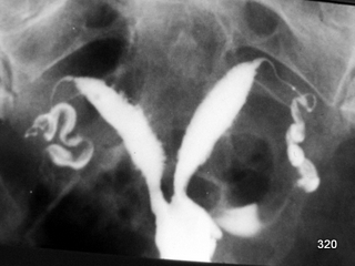
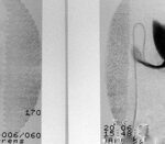
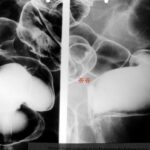
Fig. 16: X-ray imaging of the colon during filling with contrast medium and air under fluoroscopic guidance.
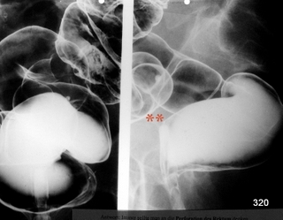
The traditional technique has been largely replaced by colonoscopy, with its indispensable capabilities for biopsy and therapy. To some extent, it has also been replaced by virtual colonoscopy in CT.
The figure shows two planes. Left: Beam path sagittal, from back to front. Right: Strictly lateral. This lateral image serves as a reminder to anyone working with patients to pay strict attention: not to press or injure the anterior wall of the rectum with the rectal tube. This risk is significantly reduced by performing a digital examination of the anal canal and lower rectum prior to the procedure (with or without X-rays). An informed patient understands all measures taken to facilitate and ensure the safety of the examination.
Fig. 17: X-ray depiction of the inferior vena cava. Where and how was it punctured?
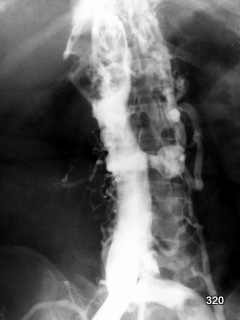
Puncture of Blood Vessels at the Groin and Contrast Medium Injection
A large filling defect at the entry point of the right renal vein suggests a
kidney tumor, most likely a
large tumor thrombus in the renal vein. This finding is not uncommon in hypernephroma cases.
Fig. 18: Imaging of the Inferior Vena Cava via Contrast Injection in a Vein
A catheter is inserted in the groin on the left side. The vena cava shows significant narrowing and displacement, likely due to a
lymph node mass, consistent with prior ultrasound (sonography) findings. Cavography, a rarely performed procedure, was conducted.
Subchapter: 3c Additional Radiation Protection Rules in Fluoroscopy
These rules particularly pertain to the examiner. This is illustrated in a
dedicated experiment. In the previous chapter, this setup was used to examine X-ray imaging. Here, fluoroscopy in specialized techniques (such as bowel function studies) is analyzed. Despite the complexity of such exams (large, dense body volumes), the challenges of radiation protection in fluoroscopy are evident.
Key Findings:
- Imaging series were captured using a C-arm.
- The experiment used the phantom shown in Fig. 10b.
- An Automatic Dose Rate Regulation (ADR) system was employed. Given the largest cross-section of the human body was irradiated in this study, the results are striking and not mitigated:
- 1 minute of fluoroscopy equals 42 X-ray images.
- 10 minutes of fluoroscopy equals 420 X-ray images.
Pulsed fluoroscopy was not used in this experiment but is an
excellent alternative to traditional continuous fluoroscopy, offering significant dose reductions.
An ECG-triggered fluoroscopy system, which captures images only during defined phases of cardiac activity, can reduce doses by up to
90% and is widely recommended for cardiac catheterization procedures.
What is ADR?
ADR (Automatic Dose Rate Regulation) automatically adjusts kV and mA to optimize image quality.
- When an object is too thick/dense, ADR increases kV (up to ~68 kV). If insufficient radiation reaches the image intensifier, mA is subsequently increased.
- While this ensures excellent contrast for dense objects (e.g., bones or contrast agents), it significantly increases radiation exposure.
Pulsed fluoroscopy offers significant radiation protection benefits. Though it produces “choppy” images, these are sufficient for examiner orientation and lead to dose reductions.
Fig. 19: Anomaly in Imaging the Inferior Vena Cava
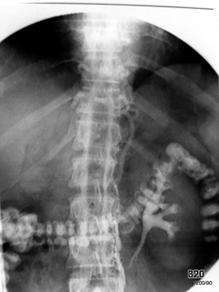
Contrast medium was used to attempt visualization. The right kidney is non-functional, and the vena cava is occluded. Blood flows through
paravertebral veins and spinal veins, forming a collateral circulation.
The filling of the colon originates from a previous gastrointestinal study, which is a
quality issue. This image is a curiosity.
Fig. 20: Imaging of the Left Kidney via a Catheter
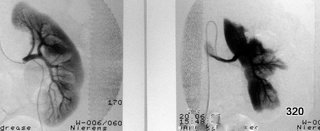
This image shows the left kidney using a catheter in the artery. The differences in images obtained during the same investigation are discussed further.
Two (!) arteries supply the kidney: one branch for the inner central sections and another for the outer cortex; no pathological significance.
Summary of Important Rules for Fluoroscopy:
- Short and rational fluoroscopy time! Avoid turning on the fluoroscopy stream and then pausing to think.
- Use the smallest possible field of view!
- Maintain distance from the patient! Step back when possible to increase the distance from the scatter radiation source.
- Wear personal radiation protection: lead apron, thyroid shield, and eye protection!
- Personal dosimetry is essential.
- Training on the device, adherence to service instructions, and monitoring compliance.
- Practice regularly with the equipment.
- Encourage continuous exchange of experience.
- Use an additional movable collimator.
- Monitor and measure backscatter in the examination room.
- Utilize modern image generation systems.
- Employ pre-programmed profiles (e.g., low-dose profiles).
- Use pulsed fluoroscopy.
- Automate documentation of the integral dose area product.
- Employ semi-transparent collimators and wedge filters.
- Utilize virtual collimation.
- Conduct radiation-free table positioning checks.
The most common errors and topics in radiation protection, regardless of the method:
- Excessively long fluoroscopy times: One of the most significant errors in handling fluoroscopy.
- When fluoroscopy is performed without the examiner being able to physiologically process the fluoroscopic images, it violates the ALARA principle. Fluoroscopy should not continue if the DL image cannot be mentally processed. Exposing the patient in such cases is essentially pointless and, roughly speaking, constitutes bodily harm.
- Failure to restrict the radiation field to only the essential and necessary area.
- Ignoring this principle often results in unnecessary areas being included in the radiation field. This not only leads to useless radiation exposure (for both the patient and the examiner) but also worsens image quality due to increased scatter radiation.
- Legally required lead aprons must have a thickness equivalent to 0.35 mm of lead. When the full weight of the apron rests on the shoulders, it can hinder breathing. A belt can help distribute some of the weight onto the hips, making it easier for the examiner.
- Protecting sensitive areas: The eyes, thyroid gland, and hands require personal protective equipment or mobile shielding. Combining a lead apron with a ceiling-mounted lead glass shield significantly enhances radiation protection for the examiner.
- Positioning the movable lead glass shield: The examiner must adjust the shield so that the top edge of the shield aligns with the upper boundary of the patient’s area being irradiated. This is especially critical when the X-ray tube is positioned above the table or laterally on the examiner’s side.
- Movable shields should be positioned near the radiation source to provide optimal protection for the examiner. Although this setup exposes the shield to higher doses, it reduces the examiner’s exposure and scatter radiation in the room.
- The use of personal dosimeters under lead aprons remains essential to monitor cumulative doses over time and ensure compliance with annual or lifetime dose limits.
- Comprehensive training on equipment operation is mandatory. This training must be disseminated to all staff and continuously updated to optimize workflows and maintain safe practices.
- Examiners must practice on fluoroscopy equipment in “dry runs” without patients before operating them. Without this preparation, examinations may result in unnecessary radiation exposure and inefficiency.
- The integration of structural and equipment requirements with application techniques benefits both patients and examiners. Effective radiation protection setups reflect the hospital administration’s commitment to safeguarding staff and patients.
- Minimizing scatter radiation from walls, ceilings, and floors is crucial. This can be achieved by maintaining a minimum distance of 1.5 meters between the radiation source and surrounding surfaces and using materials with low scatter properties.
- Employing modern image generation systems is critical. Techniques such as pulsed fluoroscopy and pre-programmed profiles (e.g., low-dose settings) significantly enhance radiation safety.
- Automated documentation of the dose area product (DAP) is now standard. This ensures accurate dose tracking and prevents underreporting.
- High-quality dose profiles: These adjust kV and mA to optimize both image quality and radiation safety. Proper training is necessary for their effective application.
- Last Image Hold (LIH): This feature allows the examiner to pause and evaluate the fluoroscopic image without additional exposure, significantly reducing unnecessary radiation doses.
- Spatial modulation: Using semi-transparent collimators or wedge filters can further reduce dose exposure and enhance image quality.
- Virtual collimation ensures precise positioning of filters and collimators without unnecessary radiation exposure. This technology is increasingly being adopted and represents a significant advancement in radiation protection.
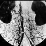
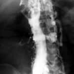
Fig. 21: Catheter Examination of the Abdominal Aorta (Main Artery)
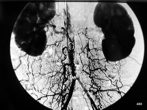
The catheter was advanced “with foresight” via the axillary artery, through an access point near the shoulder/arm. The subtraction technique highlights the contrast medium while suppressing the background. This is an inverted image, where the contrast medium appears dark.
The displayed image is a late subtraction image:
- The upper abdominal aorta is already occluded, and the kidneys are strongly enhanced with contrast.
- Occlusion of the main artery just above the bifurcation into the two iliac arteries.
- An extensive collateral circulation has formed through a broad, paravertebral venous network.
The collateral circulation indicates that this occlusion is not recent and that the body has attempted to compensate for it. However, the compensation is insufficient, and the patient continues to suffer from severe circulatory issues in the lower extremities.
Chapter 4: Computed Tomography CT (Fig. 22–25)
Fig. 22: Hip endoprosthesis (artificial hip joint) with complicated and inadequate osseointegration.
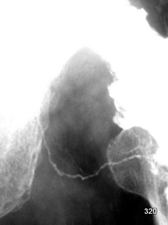
Attempted X-ray contrast imaging of a joint (arthrography). The deliberately underexposed image reveals an interesting secondary finding: drainage of the contrast medium injected into the joint space via a large lymphatic vessel.
4a The Most Important Dose Metric in CT:
Dose-Length Product (DLP)
The DLP (analogous to the dose area product in projection radiography) is easy to measure, as most devices provide this value automatically. This means that clinicians can easily familiarize themselves with DLP and use it effectively.
DLP is well-suited and superior to some other metrics, such as:
CTDI(vol) in mGy
For example, the DLP for a typical abdominal CT was approximately 900 mGy x cm 10 years ago. Today, we should aim for much better values.
What about the use of mSv? Fundamentally, the equivalent dose in mSv is an important metric, as it considers the biological effects of radiation and allows different examinations to be compared. However, calculating mSv is challenging. The more data included, the larger the potential error based on error propagation formulas.
Since the type of radiation in CT is known, one of the advantages of the equivalent dose—accounting for different types of radiation—is less relevant here.
A common question is the comparison between a standard CT examination and one performed with radiation-saving settings: the search for an optimal “low-dose CT.”
In a 2012 article in the Deutsches Ärzteblatt (Kim/Kim/Kim: Low-dose abdominal CT), the authors compared two different settings for abdominal CT. They exclusively used the effective dose in mSv. However, this question could also be addressed using the Dose-Length Product (DLP).
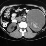
Fig. 23: Condition following surgery on the left kidney performed 40 years ago.
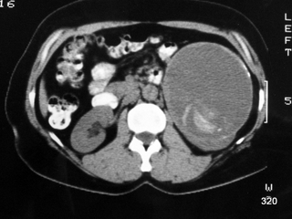
Non-contrast CT: Mass lesion (ML) in the area of the left kidney with a partially calcified peripheral rim. The ML is homogeneous, of relatively low density, but contains some (dense) hyperdense structures in the dorsal portion.
Final diagnosis: retained surgical sponge, now calcified, with a partially calcified abscess capsule.
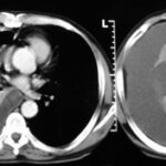
Fig. 24: Thoracic CT with intravenous contrast. Homogeneous opacity of the right hemithorax: aggressive pleural effusion.
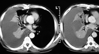
The pleura is uniformly thickened and hyperemic. There is no air or cell debris in the effusion. However, the puncture revealed pus-forming organisms, confirming a diagnosis of pleural empyema. Despite the significant compression of the lung, some airways remain ventilated, forming a residual aerobronchogram. A pronounced mediastinal shift to the left is also evident.
4b ALARA Principle in CT – Critical Reflections on “Low-Dose”
The ALARA principle is equally valid and important in CT imaging.
In CT, most patients are scanned using the same tube current (mA) and kV settings, regardless of body size. Larger patients exhibit significantly higher image noise than slimmer ones. There is a convention not to increase the dose for larger patients. Thankfully, this adjustment is not easily done, which prevents unnecessary increases in radiation exposure.
Unfortunately, there is insufficient use of lowering the dose for slimmer individuals or in areas with ideal density contrasts (e.g., lungs, bones). However, this has improved in recent years. This aspect of procedural differences will be discussed in the following chapters, starting with imaging examples from conventional X-rays:
It is well established that mA is directly proportional to dose, and reducing mA results in a significant dose reduction (albeit with increased noise). These insights are gradually being recognized. Efforts in CT imaging for the lungs and bones deserve acknowledgment.
The study cited earlier (“Kim/Kim/Kim”) exemplifies how the medical community is addressing radiation protection in CT. Time and again, research groups demonstrate that adjustments to the tube current (mA) can be made. They often report with a degree of pride that diagnostic accuracy is still achievable even with, for instance, a quarter of the usual tube current.
In pharmacology, dose determination is standardized through studies. In contrast, in radiology, the adjustment of radiation dose (e.g., turning the knob) is left to the examiner. Many physicians are unaware of this responsibility.
These considerations lead to a critical view of the term “Low-dose CT.” But what constitutes “low”? To acknowledge the propaganda-like nature of the term “low-dose,” it would be prudent to always place it in quotation marks.
Over the past years, there have been remarkable advancements in detector sensitivity, even fully utilizing all photons. However, it would be better to adhere to the common scientific approach of specifying a numerical value and unit instead of relying on buzzwords like “low-dose” (e.g., 200 mGy x cm).
Such a value could be printed at the end of a CT examination, and mandatory documentation could be enforced. This topic is highly contentious and warrants further discussion.
The Ärzteblatt addressed radiation protection early, including in:
Dtsch Arztebl.105 (2008), No. 3, pp. 41–46, SHANNOUN, F.; BLETTNER, M.; SCHMIDBERGER, H.; ZEEB, H.: Strahlenschutz in der diagnostischen Radiologie.
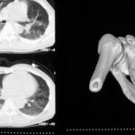
Fig. 25: Polytrauma. 3D Imaging. Scapular fractures, post-traumatic hematomas, with expelled contents from coughing.
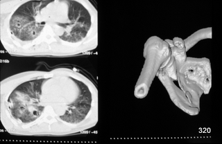
The thoracic hematoma has already been relieved by a drainage. Additionally, the lung shows diffuse consolidation with several air-filled cavities: Post-traumatic hematomas, whose contents have already been expelled through coughing. The post-traumatic nodules have transformed into cavitary structures. This phenomenon is rare in trauma cases (first described by H.G. Schmitt).
4c CT: Indications and Alternatives
- Is there a therapeutic option? If not, the indication is weak.
- What alternative methods are available?
If an X-ray examination has been performed, it is essential to evaluate it optimally. A good example is “bone metastases.” Today, no one would rely on conventional X-rays to assess bone metastases. However, if the examination has been conducted, it would contradict radiation protection principles not to evaluate it thoroughly.
Chapter 5: Interventions, Method Selection:
Sonography, Fluoroscopy (DL), or Computed Tomography (CT) (Fig. 26-32)
- Fluoroscopy (DL)
- Computed Tomography (CT)
- Sonography
Some punctures do not require any imaging guidance. A significant number can be performed with the help of sonography (ultrasound). Sterile conditions can be achieved. The main challenge is the visibility of the puncture needle. A needle model that is clearly visible under ultrasound is essential. Products from a trusted manufacturer should be carefully tested in advance in a water bath and tissue phantom.
Interventions also utilize various X-ray methods. The choice depends on the question: Which method allows for accurate localization?
When to use DL and when to use CT?
CT is the method of choice when the target region is better visualized in CT.
What is already clearly visible in DL can be punctured under DL guidance. From a radiation protection perspective, DL may offer advantages. However, all methods require careful planning and execution.
For interventions under fluoroscopic guidance, all the principles outlined in the previous chapter apply. These procedures are characterized by the close proximity to the patient. The occasionally significant doses for both the examiner and the patient demand special attention to radiation protection.
The dose area product (DAP) is a suitable metric for assessing patient radiation protection. For example, during a PTA (percutaneous transhepatic intervention of the bile ducts) with an average DL time of 15 minutes, the DAP is approximately 10,000 cGy × cm2.
How much greater is the DAP for PCTA compared to a purely diagnostic procedure? Fischer et al. (1995) estimate the dose ratio of diagnostic angiography to intervention at approximately 1:1.5. Other sources suggest values around 30% higher.
Based on the dose limits specified by radiation protection regulations (RöV) for occupationally exposed individuals in Category A, the maximum allowable number of interventions for an examiner ranges from 100 to 1,000 per year.
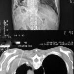
Fig. 26: Overview image, scout view, mirrored. Chronic empyema.
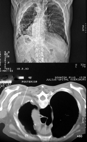
The left thoracic cavity is reduced in size. A calcified dense shadow line runs parallel to the inner thoracic wall (top and lateral).
In the CT slice, it becomes apparent that this represents the inner wall of a residual effusion (i.e., the pleura visceralis). The patient has experienced unclear fever and coughing for three weeks.
Puncture performed in the prone position at the inner edge of the left scapula. A needle placed in the residual cavity. It must not be advanced further.
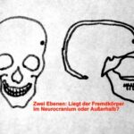
Fig. 27: Two X-ray scout views resolve many spatial challenges. Here, a special case demonstrates the limitations.
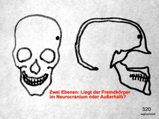
It is unclear whether a foreign object or calcified mass (tumor) is located inside or outside the skull cap. The solution is shown in Fig. 28.
Fig. 28: A slice technique resolves the issue.
Can the solution also be achieved with scout views?
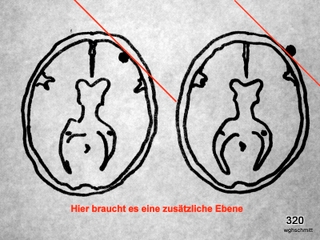
This represents a (rare) indication for fluoroscopy: finding a projection in which the shadow in question is positioned as close as possible either inside or outside the skull cap.
In other words: Is there a projection where the shadow is projected as close to the skull cap as possible or even extends outside it? This determination clarifies whether the structure is intra- or extracranial.
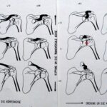
Fig. 29: The shoulder joint space is to be punctured. The most reproducible spatial planning involves the central ray.
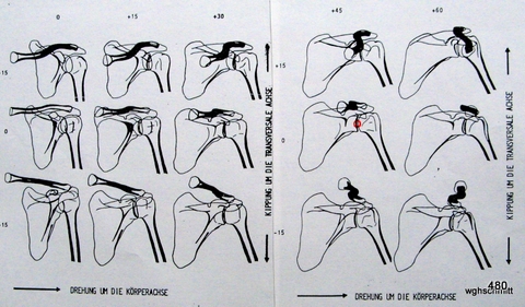
A projection is sought that separates the head from the socket and makes the joint space visible (small red circle).
The central ray could be used as an excellent pathway for puncture.
How should I position my patient’s “shoulder” so that the joint space aligns with the central ray?
A clear explanation requires projection studies. In the shown study, we observe 5 columns of different rotations along the patient axis, ranging from 0° to 60°, and 3 rows from +15° through 0° to -15°.
Fine adjustments could be made effectively using fluoroscopy.
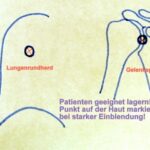
Fig. 30: Fluoroscopic guidance is used, for example, to puncture the shoulder joint or a pulmonary nodule.
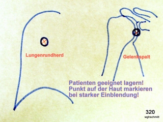
The patient must be positioned appropriately, and a point on the skin is marked under a very tight collimation.
This ensures that the puncture site aligns with the central ray, which also reduces the dose.
Using the needle for “local anesthesia,” I hold this point on the skin. The patient is informed that no intervention is taking place at this stage. Importantly, I do not move my hand into the (already very tightly collimated) radiation field.
Next, the image intensifier is moved away, and I administer the local anesthesia along the direction of the now-known central ray, followed by the puncture.
If needed, I confirm the needle position under fluoroscopy, but only after removing my hands from the needle.
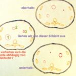
Fig. 31: Basics from CT. Three consecutive slices. Starting from the middle slice on the left side of the image, where are the three lesions located?
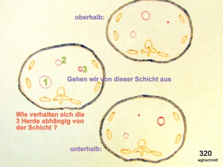
Lesion 1 becomes smaller above and below, meaning its largest extent is in this middle slice.
Lesion 2 becomes larger above and must be followed upward.
Lesion 3 becomes larger below and is not fully delineated here, requiring further evaluation downward for certainty.
5a Puncture Under Fluoroscopy?
Puncture under fluoroscopy is useful in cases where something radiologically visible (but not detectable via ultrasound or palpation) needs to be punctured.
The origins of fluoroscopy-assisted localization date back over 100 years. Foreign body searches revealed unforeseen opportunities but also introduced new challenges in radiation protection, some of which are still not fully understood by many users today.
For all forms of radiation-assisted puncture:
Careful communication with the patient is essential, as will be discussed in the next chapter.
Fluoroscopy and puncture should not occur simultaneously but rather intermittently whenever possible.
A significant advantage of this principle is the reduction in radiation dose for both the patient and the examiner, particularly the dose to the examiner’s hands.
Steps for a Puncture Under Fluoroscopy:
The simplest plan is the best.
- Fluoroscopy “precedes” the puncture: First, locate the area using X-rays, then insert the needle!
Using fluoroscopy, select the puncture site and pathway that can be reproduced after fluoroscopy is switched off.
Prefer a simple, clearly defined mathematical pathway: Keep the table perfectly horizontal as a reference plane, with the X-ray beam perpendicular to the table. This ensures reproducible conditions for the central ray (and later the needle).
- The patient may need adjustment to align with the “clearly defined” ray path. The examiner repositions the patient without fluoroscopy so that the target is optimally visible along a short and anatomically safe path.
Collimate to a very small field for two reasons:
a. Radiation protection.
b. Ensuring that the fluoroscopic field aligns with the central ray. With larger fields, rays outside the central beam diverge and no longer remain perpendicular to the reference plane (the examination table).
- Mark the skin at the entry point of the central ray. Ensure hands remain outside the primary radiation beam.
- Perform the next step without radiation: Insert the needle along a way which is identified to the central ray. This is straightforward because the entire system (see Step 1: Tube and Table) is in a clearly defined position.
During needle advancement, fluoroscopy is unnecessary unless confirming the needle tip’s position relative to the target (e.g., deviating up/down, left/right). Ideally, the needle should appear as a “dot” on the screen, aligning precisely with the target. This confirms that the needle is in the “central ray” and on course.
- A second fluoroscopic view in a usefull plane indicates the needle’s depth.
The clearly defined first view (Step 1) is crucial for easily and reproducibly defining the second view. Ideally, the second ray path is perpendicular to the first.
- Once the target is reached: Perform tissue sampling and document the procedure.
Ensure continuous communication with the patient and staff, monitor the patient, and schedule timely follow-ups. Define time intervals for follow-up checks, such as blood pressure monitoring and key symptom tracking, e.g., shortness of breath, pain, or bleeding.
5b Puncture in CT
Fig. 32: Simplest form of a CT-guided puncture. Parameter planning on the screen, with the needle trajectory confined to a single slice.
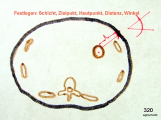
The principle applies: The simplest plan is the best.
The key to success is a compassionate reception of the patient, comfortable positioning, and explanations that alleviate the patient’s fears. The patient should also understand that the puncture will be done carefully and requires thoughtfulness and time. It is counterproductive to say, “This will be done quickly.” A puncture is not “saber fencing”: the necessary time is taken, planning is thorough, and yet we remain attentive to the patient.
Taking time to plan drastically reduces radiation exposure. In addition to verbal patient support, a medicated sedation is advisable for an interventional procedure. The effectiveness of sedation is enhanced by motivating and explaining the procedure to the patient. However, aggressive sedation for cooperation is almost always unnecessary and undesirable.
Monitoring with ECG and oximetry is recommended, especially if the patient may need to be left unattended briefly.
Like fluoroscopic punctures, CT-guided punctures can be performed with minimal radiation when applied rationally. CT punctures follow (in contrast to fluoroscopic punctures) the modern principle: the patient remains still, while we move around the patient with the technology.
Timeline:
- The examination that justified the intervention is available. The next three steps occur without radiation:
- Define the target site.
- Define the puncture path.
- Define the skin puncture site.
These three points should lie in a single plane. The reasoning is that interventions can become stressful, so a simple plan minimizes additional anxiety.
- Locate a slice where these three points can be electronically marked. Until now, interaction with the patient has been verbal only; now begins the manual interaction.
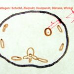
- Draw the slice on the patient’s skin. Use the CT laser to mark the selected slice.
- Mark the puncture site on the patient. This step requires measuring the distance from the midline and confirming the measurement from the table surface. The puncture site must lie along the line drawn in Step 5.
- Local anesthesia. Confirm the chosen puncture site with a single CT slice or a short spiral. Use a metallic marker or the anesthesia needle to indicate the puncture site.
- Puncture at the measured angle (Step 1) and depth (Step 1). No radiation is used during this step.
- Verify the puncture path, e.g., at two-thirds of the planned depth.
- If the needle tip deviates slightly ventrally/dorsally or cranially/caudally, correct its position. Advance the needle to the full planned depth and perform a tissue biopsy.
- Positive feedback for the patient and staff. Arrange for patient recovery and follow-up monitoring, including defined time intervals for checks (e.g., blood pressure, symptoms like shortness of breath, pain, or bleeding).
CT Fluoroscopy: Not Recommended
From a radiation protection perspective, the author strongly opposes CT fluoroscopy. It generates images approximately 20 times faster than the human brain can process. For example, if I produced images every second, I might react appropriately. However, in CT fluoroscopy, the images “rush past.”
Producing 40 images per second might show that the needle advanced by 1 cm, something I already knew. Alternatively, 40 images could be generated, and nothing happens, wasting radiation dose.
CT fluoroscopy (hopefully only exceptionally promoted by the industry) contradicts the principles of radiation protection for both patients and physicians.
A common excuse is: “This is similar to conventional fluoroscopy.” This is not true. Even in conventional fluoroscopy, advances (e.g., pulsed fluoroscopy) have mitigated its disadvantages over time.
