Artifacts also in Nuclear Medicine and Iatrogenic Artifacts
14.11.25
Dear visitor of this article,
Send me an email: Where are mistakes? What can be improved? What is unclear? What do you like? I am happy to respond.
The previous article dealt with the concept of artifacts in X-ray imaging. The images were sorted according to a simple scheme:
Bright artifacts (1) and dark artifacts (2).
For this purpose, a code for encrypting the artifacts was designed, which allows the artifacts to be sorted and searched according to various parameters.
In the following Chapter 3, the collection will be expanded to include additional classic artifacts (black and white artifacts) from conventional X-ray imaging.
There have been some requests regarding the test “Scratching off
the emulsion on the front and back of films.”
I will present additional cases on this topic.
Many thanks to Dr. Paul Gelinsky for critically reviewing the images and providing a wealth of useful advice!


Artifacts II, Chapter 3: Additional Artifacts from X-ray Imaging
It is not always easy to determine what is truly an artifact and how it originated.
Artifacts often mean waste of dose, material, and time, inconvenience for patients, and above all, risks of misdiagnosis.
Should these negative occurrences be documented? In my opinion, doing so is helpful for systematic prevention and ultimately for
quality improvement.Quality has something to do with truth and knowledge. In this context, it means optimal diagnostics with reasonable effort.
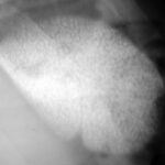
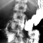
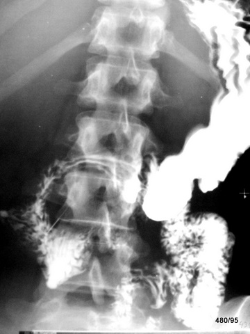
Fig. 3.01 Abdomen; Strong or even too strong contrasts? Error? Cause?
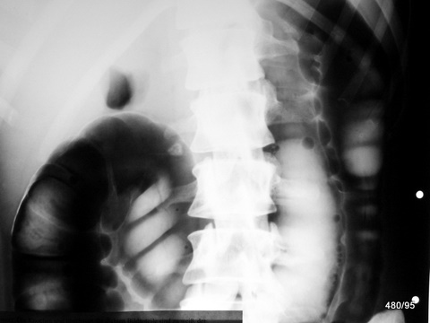
3.01: XBBXERXFBXGXLXV (Definition of this new code in Artefacts I)
Excerpt from an abdominal overview “Colon in double contrast.”
At first glance, a “good” contrast seems to be present. However, there are too many sections that are either too white or too black, making differentiation in these areas impossible.
The cause is a drastically low kV = excessively “soft radiation,” estimated at 50 kV (kilovolts);
the German Medical Association mandates 120 kV (or even higher) for abdominal imaging.
This is a serious diagnostic error because no diagnostic conclusions can be drawn from the black and white sections of the image.
Additionally, such images taken with low kV require high doses to adequately penetrate the object.
Thus, in terms of radiation protection, this is another serious mistake!
Until about seven decades ago, there was a trend of producing overly high-contrast images. However, today, this approach meets neither modern diagnostic quality standards nor radiation protection guidelines.
One could classify this image as an artifact or simply label it as a faulty radiograph.
(Chapter 5 takes a deeper look at image alterations that fall specifically under medical responsibility = iatrogenic artifacts.)
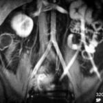
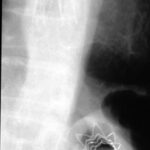
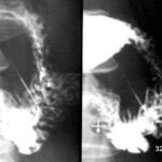
Fig. 3.02 “Black” image; meaningless information?
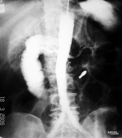
3.02: XBBXDXERXLXV
Double exposure.
Aortography and an image from a double-contrast study of the small intestine were superimposed, resulting in the noticeably dark image.
In this single image, the following can be identified: the aorta with contrasted spleen and kidney, as well as a distended duodenum with a small bowel tube positioned at the Treitz ligament.
Such an embarrassing error is rare. However, when it occurs, the workflow must be reconstructed and the causes of the mismanagement must be eliminated.
Fig. 3.03 Artifact or explainable finding?
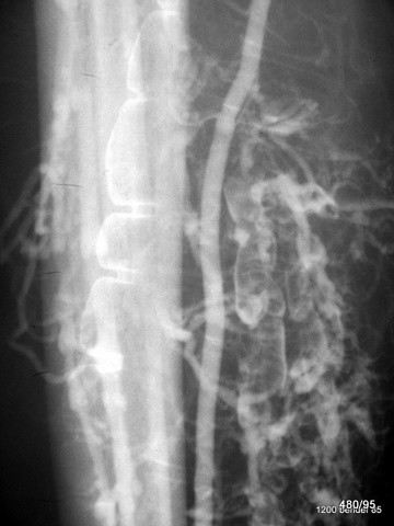
3.03: XBBXDXERXLXV
This case and the previous one are separated by both time and location. However, thematically, they are quite similar.
The haustrated colon is superimposed with blood vessels and a tubular bone.
Double exposure.
If it weren’t so frustrating and embarrassing, one might find it amusing.
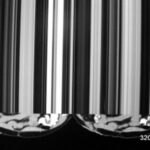
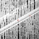
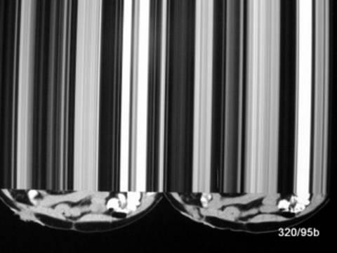
3.04 a. How can an electrical discharge be distinguished from light exposure?
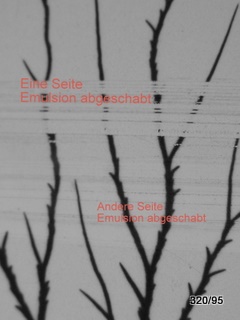
3.05
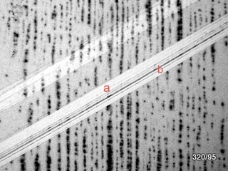
3.04 + 05: XBEXDXELXLXNXV
A reader had a follow-up question regarding image 2.19 from the previous article 11 and wanted to see it demonstrated in a different way.
Do we still need to understand this in the digital film era?
Yes, because we still encounter old films or work in regions where chemical film development is practiced. As chemical processing in this field declines, older issues become increasingly misunderstood.
On the vast majority of conventional X-ray films, the film emulsion is applied to both sides, allowing for better utilization of radiation.
The previous article stated that artificial electrical discharges
—unlike exposure to light or X-rays—
do not affect both sides of the film emulsion.
The two examples, 04 and 05, may appear different but share the commo feature that the film darkening occurs only on one of the two emulsion layers.
This can be demonstrated by scraping off a strip of emulsion from both sides of the film.
– In image 04a, the artifact disappears only on one strip—proving that the artificial darkening affects only one side and one layer of the emulsion.
– In image 04b, the result is the same: scraping one side of the film removes the film darkening, while the other strip remains unaffected except for a slight reduction of a diffuse background fog. (The red labeling in the image with “a” and “b” is misleading.)
I do not know who first discovered this phenomenon. It is likely that several people, including myself, had the idea that light (whether X-ray or visible) and electrical discharge behave differently on film and successfully sought the solution. I have found no published research on this and have not written about it myself.
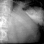
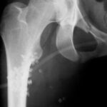
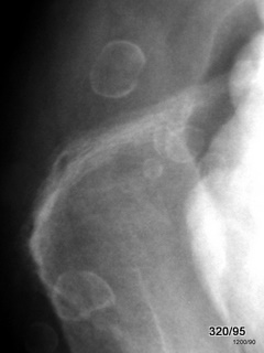
06 Car accident with total loss.
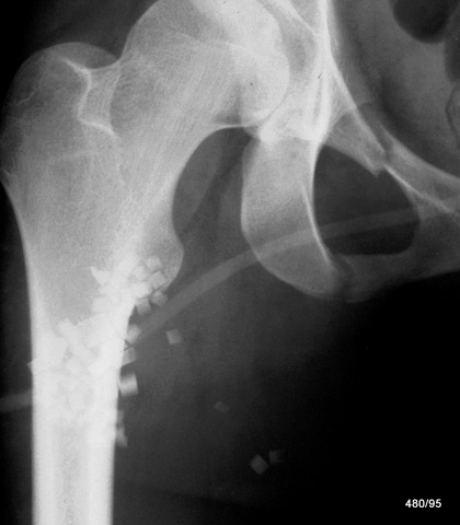
3.06: XBBXHXLXQXV
The overview image of the right hip region of the 24-year-old patient is not optimally exposed. One reason for this is incorrect centering (too medial and caudal) and improper collimation.
Besides the fracture of the anterior pelvic ring on the right side, “square-shaped shadows” are visible in projection over the proximal femoral shaft. What could they be?
Shards of safety glass!
These were found on the body surface and in the clothing.
Thus, this is an artifact caused by inadequate cleaning of the accident victim.
From the image alone, it is not possible to determine with certainty whether these foreign bodies are superficial or embedded in the tissue. The strong contrast suggests that the foreign objects are surrounded by air.
Incorporated glass fragments would appear with reduced contrast due to surrounding tissue absorption.
However, theoretical considerations are not the priority here—removing the overlapping objects is the key step.
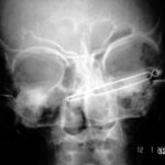
07 Artifact caused by a hair clip, quality of this examination? Additional findings?
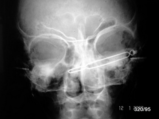
3.07 XBBXHXLXQXV
My topic in the radiation protection course leads me to collect low-quality X-ray images from various sources to use as instructional material. The indication for this particular image is unclear, but a history of ENT (ear, nose, and throat) issues is known.
Positioning and exposure should be improved.
In addition to the hair clip, “tympanostomy tubes” are visible in both eardrums, serving to maintain pressure equalization between the middle ear and the external ear canal. The connection between the middle ear and the throat—the Eustachian tube—was apparently persistently blocked.
3.08 a + b Swallowed dental root canal instrument
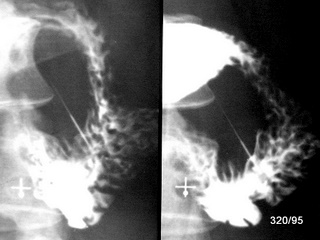
08 b
3.08 a+b: XBBXHXLXQXVXR
Metal is highly visible on X-ray due to its effective atomic number and density. The intestinal lumen can be marked using an oral contrast agent (contrast medium for swallowing) and the air already present in the intestines.
A challenge arises with the overview image. Sometimes, we do not immediately know whether an object (e.g., a needle) is located in front of, behind, or inside the intestine.
A useful technique is to rotate the patient until it becomes clear that the object is located outside the intestine.
In images a and b, the rotation is only slightly changed:
– **Image “a”**: Patient in prone position
– **Image “b”**: Patient in supine position
There is no doubt that the instrument has perforated the duodenum. Surgery was required; the procedure was performed without complications, and the patient had an uneventful recovery.
Other objects, both common and rare, that have previously been shown in these presentations in the wrong location include: a broken plastic spoon, a light bulb, a bullet, and a bitten-off pacifier.
Chapter 4: Artifacts in Nuclear Medicine, CT, and Magnetic Resonance Imaging (MRI)
So far, the focus has been on conventional X-ray imaging. However, artifacts also occur in digital radiography, ultrasound, nuclear medicine, computed tomography (CT), and nuclear magnetic resonance (NMR/MRI). Some are very old observations.
The advancement of these imaging techniques has led to impressive improvements. However, with each technological development, the range of potential errors has also expanded—both quantitatively and qualitatively.
In some textbooks on modern imaging methods, artifacts are given dedicated chapters as “pitfalls for misdiagnoses.” The level of interest in such findings often depends on how much an author has been affected by artifact-related misdiagnoses. Additionally, an author’s proximity to the imaging process influences their awareness of errors and their prevention. Medical-technical personnel have extensive experience in identifying and eliminating artifacts, ensuring that the final results are largely artifact-free.
The collection presented here is small. For CT and MRI in particular, only a few individual examples are shown. This is intended to encourage further observation and documentation of artifacts in these modalities.
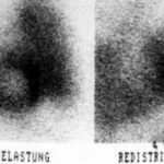
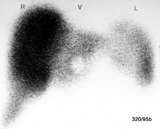
4.01: Thallium Scintigraphy; Left: Under Stress – Pulmonary Congestion
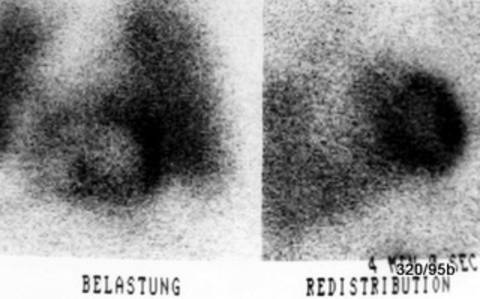
4.01: XBBXDXENXPXSXUXW (BELASTUNG = exercice)
Patient with stable angina pectoris. The stress test was discontinued due to “angina pectoris and dyspnea.”
The anterior-posterior (AP) projection (R-V-L) is shown. In the stress phase (left image):
Ischemia and intense lung uptake. The latter is an interfering artifact, yet it remains diagnostically significant.
I wanted to show you this seemingly outdated technique. Today, several other methods have largely replaced it, including emission computed tomography (ECT), MRI, CT, and ultrasound. The heart catheterization procedure has been, and remains, the gold standard. However, less invasive examinations are always performed first.
In this image, only one projection of the two typical phases (stress and redistribution) is shown.
In the left part of the image: the stress phase displays a marked reduction in uptake in the basal sections of the left ventricle.
Another striking finding is the massive increase in lung activity, indicative of severe congestion. This congestion can be quantified using other methods and is also clinically evident.
In the redistribution phase (right image): there is a clear improvement in uptake in the previously affected heart regions, confirming true ischemia rather than just a scar. Additionally, the lung congestion has resolved.
The pathological increase in lung activity appears like a disruptive artifact, but it is actually a highly significant clinical finding.
It is not my aim here to describe the full range of modern imaging techniques.
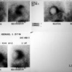
4.02: Ischemia in the Septum and Heart Apex
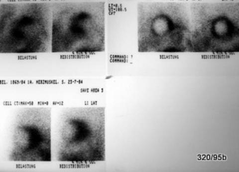
4.02: XBBXDXENXPXSXUXW (Left: BELASTUNG = exercice, right: REDISTRIBUTION)
Today, we have more advanced imaging techniques. However, for demonstration purposes, this older examination method is shown.
The two images in the upper right show the musculature of the left ventricle, both in LAO (left anterior oblique) view.
The images on the left show the stress phase, with reduced uptake in the ventricular septum and at the heart apex. In the redistribution phase (right-side images), this deficiency is balanced out. This pattern is characteristic of ischemia—reduced blood flow to the heart muscle under stress.
The two images in the upper left provide a frontal view (previously labeled by my former chief, U. Feine, as “R-V-L”). A significant increase in lung activity can be observed under stress (left image), indicating that the heart is struggling to handle blood transport, leading to pulmonary congestion.
The most likely cause is a narrowing of the coronary arteries. The heart’s own blood supply is restricted due to diseased vessels. While this reduced perfusion may not be noticeable at rest, it becomes problematic under stress and poses a significant risk of a heart attack.
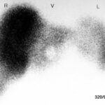
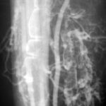
4.03 Liver Scintigraphy, Frontal View,
Labeled “R V L” (Right-Ventral-Left) – Artifact?
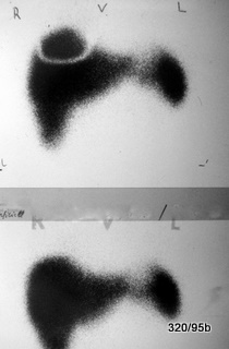
4.03: XNRXBBXHXSXUXWXQXV
Many years ago an arc-shaped activity defect in the otherwise uniformly active liver and spleen. This was caused by the metal support of a breast prosthesis, which blocked liver activity from being displayed. After removing the prosthesis, the artifact disappeared (shown in the lower image). A classic artificial artifact—unexpected but easily corrected.
Special thanks to our late mentor, Professor Ullrich Feine, Tübingen.
4.04: Liver Scintigraphy with a “Filling Defect” in the Caudal Sections of the Left Liver Lobe?
4.04: XNRXBBXHXSXUXWXQXV
Artifact caused by a belt buckle, which attenuated the radiation much more than expected.
Radioactive technetium is attached to a liver-targeting chemical compound. The radiation emitted by Tc is relatively strong, and the lower, ventral ribs do not pose a significant barrier to its penetration.
None of these artifacts are particularly surprising. However, they illustrate an important principle—one that differs slightly in nuclear medicine compared to X-ray imaging.
4.06: Bone Scintigraphy – Uptake in the Vein Wall of the Arm Used for Nuclide Injection
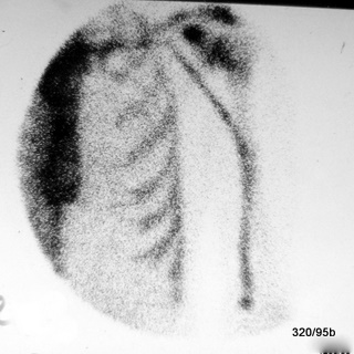
4.06: XNRXBBXDXSXWXQ
Technetium, bound to the drug “MDP,” is injected intravenously and allows for a precise and fascinating visualization of both the function and structure of the skeletal system. However, there are a few artificial pitfalls, such as this temporary uptake along the vein wall in an early phase, shortly after injection. This finding is transient and poses no health risk.
The patient in this case is the author.
Unlike radioactive substances such as iodine-131 or thallium, which became a major concern after the Chernobyl disaster, this examination is performed using a precisely measured, minimal amount of technetium (bound to MDP). Technetium has a half-life of six hours, meaning it decays relatively quickly. Its biological half-life is even shorter. The detection capability of the gamma camera is excellent, as it is highly sensitive.
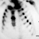
4.08: Rib Series Fracture and Sternum Fracture in Bone Scintigraphy
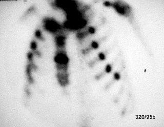
4.08: XP No artifact, no artificial finding, but a pathological condition. Post-resuscitation state. The 17-year-old patient suffered a cardiac arrest. Three weeks after resuscitation, he is doing well and has only minor complaints related to the aftermath of the procedure; he is able to breathe properly and cough effectively. However, multiple rib fractures are not always tolerated so easily.
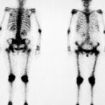
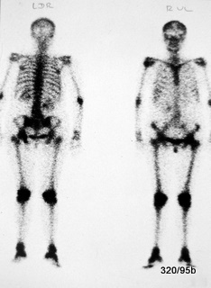
4.09: Unusually “Beautiful” Bone Scintigraphy – Superscan
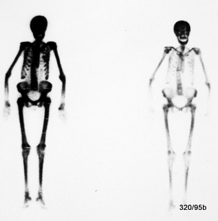
4.09: XP Until proven otherwise: Not an artifact.
What stands out is the unusually intense visualization of the skeletal system, particularly in the skull and mandible. No artifact or examination-related error is apparent.
Our French colleagues often describe such images as “trop bel image” (too beautiful an image).
However, one must consider whether such findings indicate an underlying generalized pathology.
Particular attention should be given to the localized lesion in the lower thoracic spine (BWS) and the increased uptake in the skull and facial bones.
4.10: Fact or Artifact?
4.10 XP Not an artifact, but a pathological finding.
Pathological Increased Activity in Bone Scintigraphy.
The abnormal increase in activity affects the periarticular skeletal regions, including the periphery, particularly in the knee joints and foot joints. Additionally, there is a patchy increase in activity in the skull vault.
Further diagnostics, including a bone marrow biopsy, confirmed a diagnosis of chronic myeloid leukemia (CML).
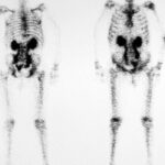
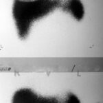
4.11: XP Urinary Retention in Bone Scintigraphy
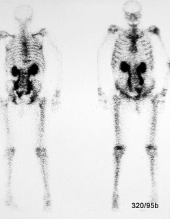
4.11: XP. In this bone scintigraphy, there is a striking massive uptake in both renal pelvises/kidneys and a bilateral urinary retention in the ureters.
The left image represents the dorsal view, while the right image shows the ventral view.
Noteworthy findings include: bilateral urinary tract obstruction and a urinary bladder displaced to the left (or possibly with a large filling defect). Further information should be obtained—has an ultrasound examination been performed? Additional diagnostics should be pursued.
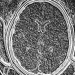
4.12 Image Disturbance in Computed Tomography (CT)
4.12 XBBXGXCXKNXLXR
Artifact probably at the computational level. Internally referred to as the “sliced fig” phenomenon.
This is a rare disturbance in computed tomography and represents issues that cannot be resolved purely through logical reasoning.
Such cases require specialized knowledge in both hardware and software.
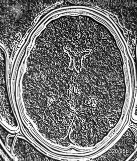
4.14 Ghosting Artifact in MRI (Magnetic Resonance Imaging)
4.14 XMRXCXGXKNXO
A ghosting artifact in MRI refers to a laterally displaced repetition of the image along the phase encoding direction, which is induced by movement such as heartbeat and respiration.
To mitigate this, triggering, breath-holding, bowel immobilization, or the use of an unsaturated saturation pulse of 600–800 ms in the “phase encoding direction” can be effective.
4.13: Artifact in the Creation of a CT Document
4.13: XBBXGXCXKNXL
Compare 4.12 – humorously referred to by us as “acute height growth.”
Artifacts II, Chapter 5: Iatrogenic Artifacts? Classification?
How should these “cases” be classified?
What exactly can be considered an iatrogenic artifact? We do not want to go so far as to classify every medical intervention as an artifact.
Classic procedures such as contrast-enhanced examinations or angiographies form a separate category.
A “separate category” could mean that these images already have an artificial, almost artistic quality—something that does not naturally exist.
Here, ingenuity has been used to bring hidden structures into the light.
However, even the standard (native) X-ray image is something that became possible only through human intelligence—something that we have since applied, hopefully wisely and for the benefit of patients.
Yet, we also encounter pitfalls.
By convention, a radiograph itself, even when combined with contrast administration, is not classified as an artifact.
However, classification becomes more challenging in the following cases:
- Atypical or unsuccessful therapy?
- Abandoned therapeutic approaches, i.e., outdated methods—artifacts?
(See pleural plombage under “Thorax and Pleura III”).
We invite discussion on whether these images should be considered historical medical documents or rather evidence of individual or collective malpractice.
The question mark in the chapter title is significant.
Each person should form their own opinion: Is this an artifact?
Is it a routine medical procedure?
Where is the boundary between standard practice and malpractice?
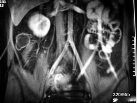
Fig. 5.01a + b: Abdominal Lymph Node and Spleen Contrast Enhancement Many Years After Examination?
01b: Enlargement from a. – Spleen
5.01: XPXMM
Thorotrastosis;
Liver, spleen, and lymph nodes retain this contrast agent for many years after application.
In article 15, “Colorful X-ray Images,” a case of
Thorotrast extravasation was presented, showing a persistent contrast medium depot in soft tissues adjacent to a duct system.
For the patient shown above, angiography was performed due to a brain tumor, which was subsequently surgically removed and never recurred.
However, the name of this contrast agent is associated with what is likely the greatest catastrophe in radiology.
The fatal long-term effects were due to the persistent storage of this radioactive element in the reticuloendothelial system (RES): spleen, liver, and lymph nodes,
as well as the potential for inducing neoplasms over long periods.
(For more on the discovery of thorium, see WGHS: Mme Curie in the article about the pioneers of humanity.)
Since this hazardous contrast medium has not been used for 70 years,
the number of remaining affected patients is now extremely small.
However, it remains important for our understanding:
What does such a medically induced splenic alteration from decades ago look like?
Now, dear readers, we turn to a different case—one unrelated to Thorotrastosis and not affecting the spleen, but involving a foreign material as the pathogenic agent.
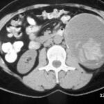
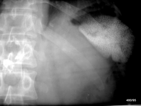
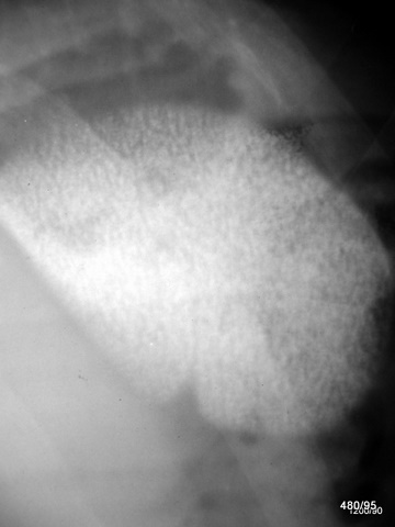
5.02: Twenty Years after Kidney Removal
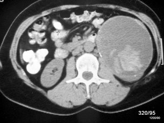
5.02 XIIXQXVXW
Retained Surgical Sponge – Abscess.
A nightmare scenario for any surgeon is leaving surgical materials or instruments inside the patient. In this case, the incident occurred at a distant location and dates back two decades.
The foreign body has likely undergone calcification and is situated within an abscess cavity, whose capsule has partially calcified.
We do not wish to downplay the patient’s suffering. It remains unclear why the diagnosis was only made after so many years. The most probable explanation is inadequate medical follow-up. Additionally, the surgical material was not marked in a way that would have made it easily identifiable on X-ray imaging.
The mass should have been clinically noticeable. Ultrasound or CT imaging was either unavailable or not utilized.
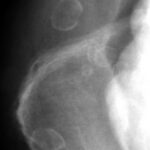
Fig. 5.03: Layered Calcifications Projected onto the Right Iliac Crest Region
5.03 XIIXQXVXWXH
These are multiple structures with layered calcifications (or could it even be fully developed heterotopic bone tissue?).
They are often located in areas that are not considered proper injection sites—frequently within fatty tissue.
Old injection abscesses in the gluteal region.
These findings are often incidental, showing no clinical activity, and should generally be left untreated.
The painful events following the injections are not always remembered. However, we do not wish to downplay the unnecessary suffering of patients.
For us, such findings serve as a constant reminder to avoid incorrect intramuscular injection techniques.
(Under the impression of such cases, I try to avoid gluteal intramuscular injections whenever possible—especially in obese patients—and instead opt for the lateral portion of the quadriceps femoris.)
(See also article 03, “Fracture Healing,” where pathological ossifications are demonstrated.
The case in 5.04 is also similar, as it demonstrates a septic complication following surgery.)Septic and aseptic complications following injections and surgeries are discussed in detail in an excellent article in Deutsches Ärzteblatt 109, Issue 24, June 15, 2012, by Holland et al.
They reviewed a large number of treatment errors following injections.
Surprisingly, a significant number involved glucocorticoid (cortisone) injections—despite their generally beneficial effects, they are not without risk when injected locally.
Various handling errors were noted. However, the most common mistake was the failure to recognize an infection.
This is particularly relevant in gluteal injections, where it is challenging to ensure proper muscle penetration in obese patients, and infections can be harder to detect.
What can we learn from Holland et al.?
– Special caution regarding septic (and even aseptic) complications following cortisone injections!
– Strictly assess whether the injection is truly necessary.
– Adhere to the highest standards of asepsis.
– Closely monitor patients—this often means simply listening carefully to them.
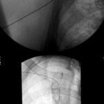
5.04a Position of an Arm Vein Catheter?
5.04a XVXWXLXKNXHXQ
The venous catheter inserted from the right antecubital fossa deviates into superficial veins at the shoulder level, instead of following the intended path through the subclavian vein into the superior vena cava. This means the catheter does not fulfill its intended function.
This is a “technical artifact”—a positioning error that must be recognized and corrected without harm to the patient; see 5.04b.
To correct the catheter misplacement, fluoroscopy is useful. However, due to radiation exposure to both the patient and the examiner, its necessity should always be carefully evaluated. Fluoroscopy should be performed with the smallest possible field and in pulsed mode (see article 10).
5.04b Same Case.
Top: Incorrect Positioning; Bottom: Corrected Venous Catheter Placement
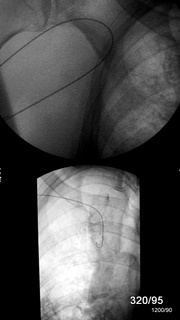
5.04b XVXWXLXKNXHXQ
In the lower image, after correction, the catheter tip is now properly positioned in the superior vena cava.
Central placement is essential, for example, in the administration of medications.
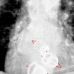
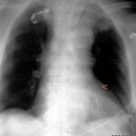
5.05: Where is the Nasogastric Tube Positioned?
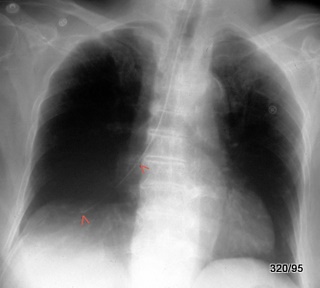
5.05 XINXVXWXLXKJXHXQ
This nasogastric tube (marked by red arrows) did not follow the intended path from the pharynx into the esophagus. Instead, it was misdirected through the larynx and trachea, advancing through the right main bronchus all the way into the periphery of the lung.
Such misplacement usually triggers a strong cough reflex. However, in some cases, this reaction may be mild, the patient may be extremely cooperative, or their discomfort may not be taken seriously.
Immediate action:
The misplaced nasogastric tube must be removed immediately before complications (such as lung injury) occur.
Where should a nasogastric tube be positioned?
In the stomach! Ideally, for enteral feeding, the tube should not rest in the gastric fundus (where it tends to coil up) but rather in the main body of the stomach (corpus) or even near the pylorus (antrum).
If the patient assumes a right-side position, the feeding solution is transported efficiently and does not accumulate in the fundus.
A separate discussion has demonstrated how uncomfortable fundal accumulation can be for patients. The fundus lies far posteriorly and tends to fill when the patient is in a supine position.
Feedback has indicated that this is an important clinical insight.
For aspiration in a supine position, the tube should first be placed in the gastric fundus, as fluids accumulate especially in the dorsal portion.
However, the tube should not be allowed to coil or kink in the fundus, as this compromises effectiveness.
Once the fundus has been properly emptied and rinsed, the tube will advance more easily towards the pylorus.
Nasogastric tubes should never twist or kink—not in the pharynx, not in the esophagus, and ideally not in the stomach.
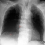
5.06: Practice Question: Where is This Gastric Tube Positioned?
5.06 XINXVXWXLXKJXHXQ
Gastric Tube Misplaced in the Left Bronchial System (marked by red arrowhead).
What to do? Immediate retraction is required.
In addition to this critical finding, there are also common, harmless artifacts: The thorax is superimposed by two ECG electrodes.
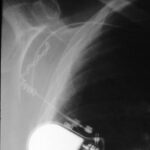
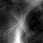
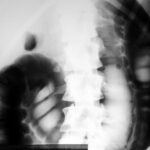
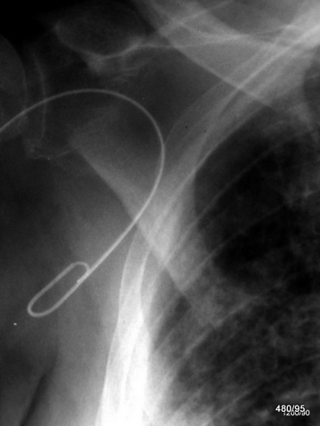
5.07 What Are the Disadvantages of This Pacemaker Unit?
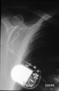
Rare Complication:
An unusually mobile pacemaker unit not only moves “back and forth” but also performs repeated rotational movements in the same direction.
As a result, the pacemaker lead outside the device has become coiled in a spiral and displaced.
The exact location of the lead tip is difficult to determine due to the film’s density.
5.08 Different or Similar Problem?
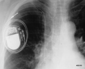
5.08: XBBXERXHXIBXKJXLXQXSXW
One of two leads wrapped around the pacemaker unit,
with at least one lead tip displaced.
In this rare case, the pacemaker unit also rotated multiple times in the same direction,
causing the atrial lead to coil around the device and become displaced.
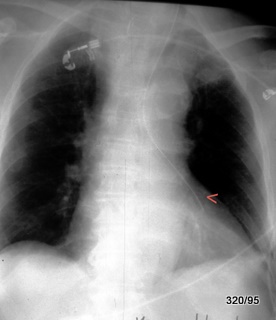
5.09 Highly Unusual Lead Placement
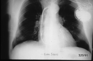
5.09 XBBXERXHXIBXKJXLXQXSXW
The situation is complex, as an additional (moderately visible) electrode, which is non-functional, is located in the right ventricle.
Another electrode is positioned in the right atrium.
A third electrode is very difficult to detect; it is marked by fine dotted structures.
Instead of following the expected path—passing through the tricuspid valve from the right atrium to the right ventricle—
this lead is misplaced in the coronary sinus, one of the major veins that return blood from the heart muscle to the right atrium.
(The corresponding arteries, the coronary arteries, originate from the proximal section of the aorta at the aortic bulb.)
Conclusion: The lead is incorrectly positioned in the coronary sinus
(the venous return pathway of the coronary circulation).
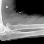
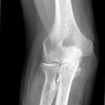
5.10a and b: Foreign Body in the Area of the Right Elbow Joint
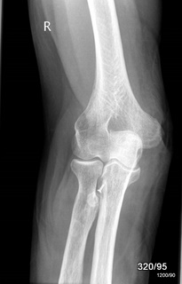
10 b: Lateral View to 10 a. What is the Small Metal Object?
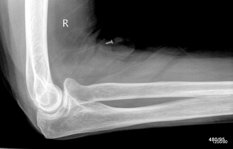
5.10a and b: XBBXERXHXKNXQXW
In the a.p. image, a structure is projected, of which only the small, proximal metallic part is clearly visible and projected onto the ulna.
In the second view (b), the superficial location is clearly visible.
The continuation of the small metallic tube is also shown in a plastic tube with low contrast.
It is nothing other than a lying venous cannula, which is
mostly made of plastic material. Although it is somewhat artificial, it has been deliberately and artfully placed. Not an artifact and not to be misunderstood as such.
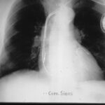
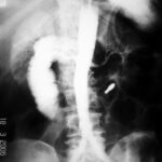
5.11: Esophageal Cancer. Post-Therapy Condition for Restoring and Maintaining Patency. Complication
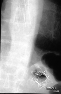
5.11: XIBXBBXERXHXKJXQXW (XIB = Iatrogenic Artifact Despite Best Intentions…..)
What is this strange flower projected onto the fundus of the stomach?
One of the two stents in the esophagus (inserted due to tumor-induced stenosis) has become dislodged and lies relatively freely movable in the fundus of the stomach. This axial projection of the displaced stent is the result of its movement.
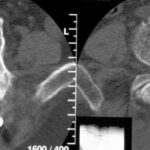
Where is the screw is supposed to be positionated?
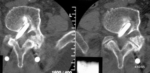
5.12: XIIXBBXERXHXKJXQXW (XII = Iatrogenic Artifact Due to Ignorance……)
The spine should be fixed using two steel rods in the back muscles (M. erector trunci). These rods are cut across dorsally by the small vertebral joints as white round areas. Typical CT artifacts from such large metallic objects (beam hardening effect, see Wikipedia and W. G. H. Schmitt, M. O. Mahmalat, H. K. Beyer: The Measurement Accuracy of Computed Tomographic Densitometry in the Vicinity of the Pelvic Skeleton Fortschr Röntgenstr 1987; 147(1): 34-38 Georg Thieme Verlag Stuttgart · New York).
From these rods, several vertebrae should be spatially fixed with multiple screws. These screws are intended to be placed in the pedicle (in the root of the arch), i.e., in the transition from the vertebral body to the vertebral arch, and anchored in the corresponding side in the vertebral body. During insertion, the pedicle can be easily localized on the X-ray image or under fluoroscopy.
ROY-CAMILLE, RAYMOND is credited as the inventor of this method. Important further developments of this internal fixator were made by W. Dick (Basel). The method is also combined with vertebroplasty and kyphoplasty. In the latter — now preferred — method, the collapsed vertebra is first straightened through balloon dilatation. This “cavity” is then stabilized with cement.
In our case, at least one screw misses the pedicle. It cuts through the spinal foramen. The concept of the method was not to do this. The tip of the screw lies too far medially in the vertebral body. It narrows the spinal canal and also the right intervertebral foramen. The screw tip in the vertebral body is loose (wide resorption margin). The screw may have broken off.
I have personally only seen such a misalignment of a pedicle screw once.
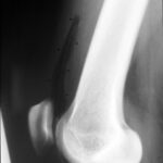
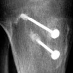
5.13: “Do these old bone screws rust?”
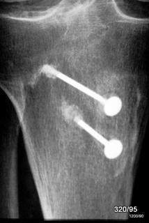
From the collection of historical rarities. The operation took place 7 decades ago and was performed during the pioneering days of osteosynthesis. Two metal pins, likely with threads at the tips, were inserted into the tibial head, with the metal at the tip apparently dissolved due to oxidation. They are rusted.
Due to the constant engagement with osteosynthesis materials (e.g., the Osteosynthesis Working Group, AO, Research Institute in Davos), complications of this type have been excluded for many years.
5.14: Air and “Tube” Above the Patella
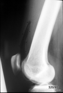
5.14: XKNBBXERXDXQXW
It is not an artifact, but a normal status. XKN = Disease value: No!
Postoperative X-ray image. The suprapatellar recess is filled with air and is therefore easily visible, unlike a normal X-ray image. It is marked by black dots. The recess is part of the knee joint capsule. Inside the lumen (the “open space”) of the recess, there is a “only weakly shadowing” drainage.
Overall, an ” iatrogenic” finding, perhaps unusual, but not irregular.
5.16: Three (Artificial) Starr-Edwards Valves in the Heart
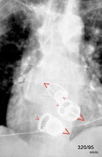
5.16: This is not an artifact. It is certainly a historical document, a surgical intervention, but one that was very helpful for the patient. The valve ring can be closed by the ball.
This is also a “medical historical image,” as this type of heart valve has been replaced by more modern mechanical models, and partly by valves made from biological material.
Here, the mitral valve, tricuspid valve, and aortic valve have been replaced.
In this image, we can see that the two atrioventricular valves are open, while the aortic valve is closed. The aortic valve is the topmost of the three prostheses.
I am showing this image as a homage to the two inventors and also to document our difficulties with spatial understanding: How do we visualize the position of these valves?
An X-ray image of a ring could have two positions: the left edge of such a ring could either be further forward or further back.
How are the valve rings positioned in our case? More precisely: In which direction is the blood flow? Is the blood flow coming toward us or moving away from us?
I have indicated with large and small arrows that the blood flow at all three valves is coming toward us, meaning that the basket holding the ball is closer to the viewer in all three cases; the valve rings are farther away. Thus, we can imagine how we are looking into the valve ring: against the blood flow.
This image of the artificial heart valves should illustrate that there are often two possible solutions in X-ray procedures. The answer, which one is correct, requires knowledge of anatomy. The answer can also be provided through additional imaging planes and a series of more complex techniques, such as contrast-enhanced imaging or echocardiography.
One method that helps overcome this dilemma would be stereo X-ray.
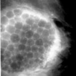
5.15: Aspiration of a Cyst in the Breast.
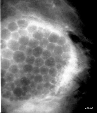
5.15: XIBXBBXERXDXQXW (XIB = Iatrogenic Artifact Despite Best Intentions…..)
By puncturing mammary cysts, the harmless nature can be confirmed* and these cysts can be made to disappear simultaneously.
Here, a large cyst was partially emptied. After air was introduced, some air remained free in the tissue to the right of the cyst. A foam formed due to the combination of the remaining cyst fluid and air, which is shown here. The foam bubbles flatten against each other, resulting in polygonal structures.
Solution: Partial refilling of a cyst with air. Due to the superimposition, some of these bubbles have a dense center, which corresponds to the intersection of additional foam bubbles above them.
An artifact, whose nature was indisputably proven in a second plane (where a mirror separates the air from the remaining cyst fluid). The therapeutic measure is not optimal, but no complications were expected, and this was confirmed. Palpation remained significantly and persistently improved, which relieved the patient.
Due to the incomplete nature of the procedure, this finding will have to be categorized under artifacts.
* Today, further methods are available for this issue, and the cyst would have been displayed sonographically before the procedure. Sonography was involved in the further course of treatment.